Fall Protection and Walkability: Analytical Methodology for Lattice Towers

Written by: Sathish Konduru, P.E., M. ASCE, Principal Transmission Engineer
Disclaimer: This article is intended for a technical audience in the analysis, design, construction, and maintenance of electrical transmission line structures. The content was originally presented at a technical conference (2022).
When combined, OSHA 1926.502 and IEEE 1307 provide requirements and considerations for qualified electrical workers to safely climb transmission and distribution structures. Meeting these requirements is especially challenging for transmission line lattice towers, as most were designed and constructed prior to these standards. Most industry-specific transmission line design software are incapable of proper analysis; therefore, manual calculations must be performed to determine the viability of safely climbing and anchoring to these structures.
This article provides a brief overview of these requirements, an approach to selecting walkable members and anchoring points, and practical methods for calculating the structural capacity of these structures for climbing. Calculations will include the necessary loading requirements for anchor points and the combined axial and flexural calculations for walkable members using ASCE 10-15 and AISC 360.
Reviewing the Requirements
As per OSHA standard 1926.502(d)(15) and IEEE 1307-2004 requirements, the anchorage points on the existing lattice towers should be used for attaching fall arrest equipment. These locations should be capable of supporting at least 5,000lbs per worker attached. These locations should be designed, installed, and used as part of a complete personal fall arrest system. A safety factor of two should always be maintained. OSHA standard 1926.502(d)(16) defines a fall arrest system as a system used to stop a fall. It should be designed to support the arresting force of a worker up to 900lbs when a body belt is used and up to 1,800lbs when a body harness is used.
Typically for any new lattice tower design, anchorage points for fall arrest anchor systems are included in the plan and are designed for a 5,000lbs fall load to meet OSHA requirements. However, when evaluating existing lattice towers for anchorage points, some utilities chose to use the OSHA standard 1926.502(d)(16) by taking the anchorage value depending on the fall arrest system used and factoring it by two. For example, if a body belt is used as part of the fall arrest system, then the anchorage design force can be limited to 1,800lbs, which is 900lbs times the factor of safety of 2. Similarly, if a body harness is used, the fall anchor load is chosen to be 3,600lbs.
Fall Protection Analysis
The fall protection analysis is performed using the industry standard software suite produced by Power Line Systems (PLS). The step-by-step procedure for performing fall protection analysis is:
1. Weather case – Depending on the region where the tower is located, the appropriate maintenance weather case is selected.
2. Anchorage points – Based on discussions with the Construction and Maintenance team, anchorage points on the tower are identified.
3. Tower model – Once the anchorage points are determined, the existing lattice tower is modeled using the TOWER software.
4. LCA generation – The TOWER model, with set and phase labels defined at the anchorage locations, is then inserted into the PLS-CADD software to extract the .lca load file.
5. FE structural analysis – After the .lca load file is generated from the PLS-CADD software, it is loaded into the TOWER model to perform the finite element (FE) analysis. If any member is shown as overstressed at the anchoring location, then that joint is not qualified for safe anchorage.
Walkability Analysis
After the tower analysis is performed, the results from the TOWER output are imported into the walkability analysis spreadsheet program, where the combined axial and flexural capacity ratios are calculated. The following list explains the calculation procedures used to calculate the flexural capacities of single-angle members per AISC 360 (2010) and ASCE 10 (2015), respectively.
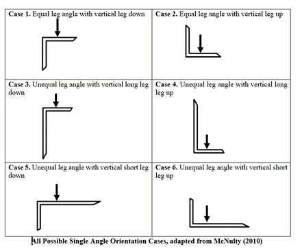
1. Angle orientations – Flexural capacity of the member varies depending on the orientation of the single angle when a vertical load is applied around one of the geometric axes. There are six orientations possible for the single-angle members:
2. Sign convention and terminology – Like any other structural calculation, it is important to establish the sign convention of the loads first. This way, when combined stress ratio calculations are performed per AISC 360 (2010) section H, results from the forces at heel and toe locations are accurately achieved.
3. Section property calculations – To determine the flexural capacity around the principal axes, it is required to calculate the section modulus properties of heels and toes with respect to major and minor principal axes.
4. Applied bending moment and flexural capacity – Once the sign convention and section properties are established, the bending moments are calculated. This is done by imparting the vertical load from the worker on the inclined member with simultaneous wind pressure acting on the outstanding leg of the angle. After the applied bending moments are calculated and resolved into principal axes, based on the applicable orientation case, flexural capacities about major and minor principal axes are calculated according to AISC 360 (2010) section F10.
5. Applied axial force and axial capacity – TOWER software calculates the axial compression and tension capacities per ASCE 10 (2015) sections 3.6 and 3.10, respectively. Axial forces and capacities are imported into the spreadsheet calculator from the TOWER output.
6. Combined axial and bending unity check – After importing the axial force and axial capacities from TOWER and calculating the bending moments and flexural capacities, the combined axial and bending unity ratios are calculated per AISC 360 (2010) section H2, and combined Stress Ratios (CSR) are calculated at each of the three critical locations (heel, long toe, short toe). If any of the CSR values are greater than unity, then that member is noted as unacceptable for walking, which is then shown as unacceptable for walking in the walkability drawings discussed below.
Fall Protection and Walkability Drawings
Figure 1 shows a summary for an example tower. In column three, the angle orientation case is selected for each member. Then the orientation case selection is combined with stress ratios and reported in the last column. This shows if the member is acceptable for walking or not. The resulting data is then transformed into drawings like Figure 2.
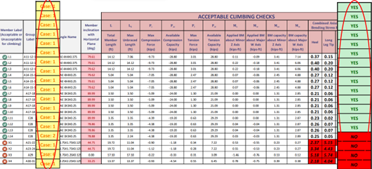
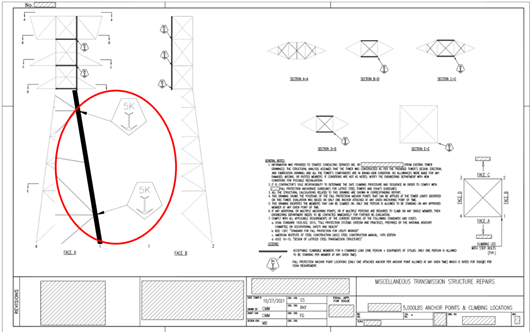
Figure 2 shows the drawing of the tower overview and highlights the safe anchorage points along the member for walking.
Once this process is complete, the drawings are submitted to the maintenance crew for use.
To safely meet requirements for selecting walkable members and anchoring points, and to execute practical methods for calculating the structural capacity of these structures for climbing, reach out to Westwood’s transmission engineering team.
. . .
Read the full white paper in the ASCE Library.
Corresponding Author: Rebecca Knowlton Fournier, P.E., Stantec
Published online: September 20, 2022; Fall Protection and Walkability: Analytical Methodology for Lattice Towers

