Increase Transmission Line Lightning Resilience

Utility developers work hard to build transmission lines that can withstand various weather elements to reduce power outages for their customers. One weather element that can greatly affect infrastructure is a lightning strike. When a transmission line experiences a lightning strike, the electrical energy contained within the strike seeks earth ground potential. Designing a transmission line that has a low impedance path to ground improves the probability that the energy contained within the strike will be channeled to the ground. This avoids a flashover condition that can cause a power outage or damage to the transmission line. To improve line performance and tolerance to lightning strikes, engineers perform soil resistivity studies and design a custom ground system at each structure of the transmission line.
What is soil resistivity and how does understanding it support a more resilient transmission line?
One important concept in the design of a transmission line is building a structure that has low footing impedance to ground. Understanding the electrical impedance properties of the soil, in which each transmission structure is placed, is a necessary step to designing an effective ground system. This soil property is referred to as soil resistivity.
Soil resistivity is the soil’s resistance to electrical flow provided by a volume of soil and is commonly expressed in units of ohmmeters. Soil resistivity is location-specific and varies due to the moisture content, composition, and temperature of the soil. Resistivity values can vary from less than 10 ohmmeters in clay and loamy soil to values over 3,000 ohmmeters in sand and rock. Convention states that lower resistivity values are preferred as less extensive grounding is required to obtain a low impedance connection to ground. A useful resource to better understand the concept and the methods that are used to measure soil resistivity can be found in IEEE’s standard #81.
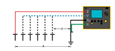
Photo: 4-pole Earth-impedance measurement (or "lattice network" measurement).
Measuring the soil resistivity at each structure allows engineers to design grounding configurations unique to each structure. Transmission line owners commonly have standards which require a maximum allowable structure footing impedance at each structure. Utilizing soil resistivity values, engineers design and predict the as-built structure footing impedances by varying the number, type, depth, and quantity of the grounds to obtain these requirements.
What is the ground system and why does it need a ground well?
The grounding system is comprised of conductive components that connect a transmission structure to the ground with a low impedance path. Typical ground systems include welded connections to the structure with stainless steel bolted connections, conductive bonding, copper wire, ground rods, and ground enhancement materials (GEM). The “connection” to earth is often accomplished with the use of ground rods or the use of ground wells, which vary in depth and are often in the range of up to 100 ft. As you can imagine, drilling multiple deep wells is expensive; therefore, by understanding soil resistivity and varying the design accordingly, engineers can create cost-effective and efficient designs by adjusting ground system configurations per structure.
Creating a transmission structure that is tolerant to lightning strikes is a delicate but common practice. Through quality ground resistance evaluations and the correct placement of a grounding system, a transmission line can become more reliable and resilient for the owner and their customers.
Contact us for soil resistivity evaluations and engineering support on your reliable and resilient transmission line.


